Overview
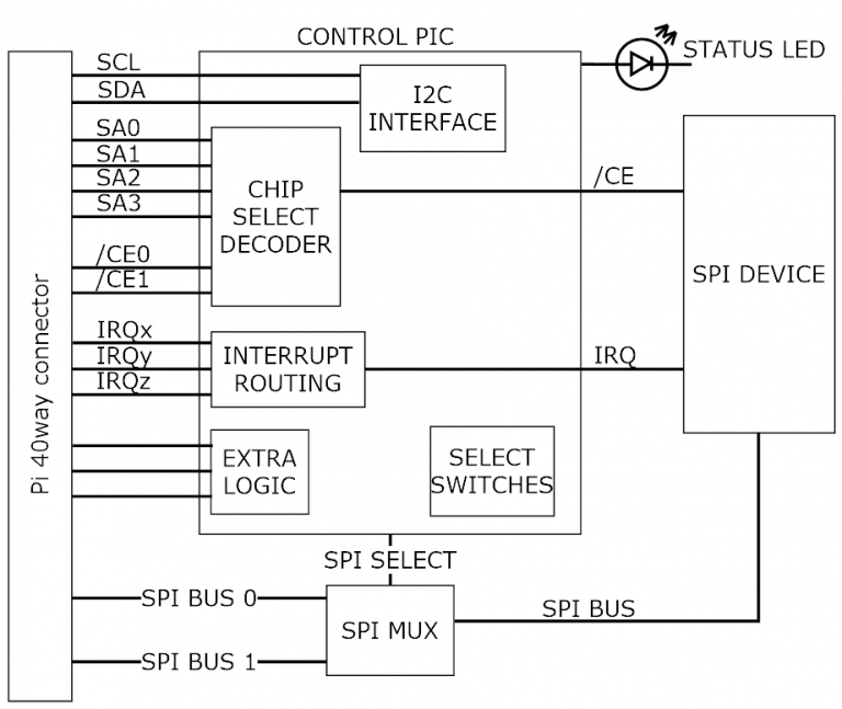
This shows the control overview of the PIXIE board.
The select switches give each PIXIE board a unique identity.
The Raspberry Pi communicates using the I2C bus to configure the PIXIE board.
The sub address (SAx) signals, interrupt signals (IRQx) and extra logic signals are connected to the GPIO pins of the Raspberry Pi.
Either SPI0 or SPI1 bus is routed to the board devices
The design goal of the PIXIE board range is to provide the user with a board that has a common footprint, uses no configuration links, and once assembled into a stack with the Raspberry Pi, can be configured and used without the need to make any further physical changes except for wiring in the connectors. All boards use 3.5mm two-part pluggable terminal blocks which in the event of a board change or other upgrade, can be simply unplugged without the need for a screwdriver.
IT IS NOT A HAT
The boards are not HAT’s, their biggest difference is that you can stack up to 16 onto the Raspberry Pi and they all use the SPI busses for maximum software access, nor do they use the HAT configuration memory.
More SPI devices
This concept is achieved by the use of some of the GPIO signals to provide additional address signals used for decoding the SPI chip selects found on the 40-way connector. You can have up to 4 additional SPI address signals per SPI bus, these are qualified by the onboard hardware decoding to give you up to 16 possible decode addresses for each SPI bus chip select. So, for SPI0 it has 2 chip selects, that is 32 possible devices, for SPI1 it has 3 chip selects, that is 48 possible devices, 80 in total which is more than most needs.
Each board can be configured to use as many of the address signals as it requires as well as which chip select the board will use.
To facilitate this sub address system requires changes to the SPI device driver and rebuild the kernel or use the precompiled SPI device driver and install it on the Raspberry Pi to replace the current one.
Configurable
Each board is software configurable from the Raspberry Pi using a simple command line application called “PixieBoard”. Each board is given a unique identity which is set by the small piano key switch allowing each board to be numbered 0 to 15. The board is configured over the I2C bus using a base address of 0x10 plus the value of the piano switch giving a range of unique I2C addresses from 0x10 to 0x1F. Each board can then be accessed individually and configured as required.
All the configuration values for each board are stored in EEPROM memory on the board so once it has been configured it does not have to be reloaded whenever the board is power cycled.
The key configurable items of each board are:
- Which SPI to use, SPI0 or SPI1
- Which chip SPI selects to use, CE0, CE1 or CE2
- Which SPI sub address signals to use and the sub address value to decode.
- Which GPIO will receive an interrupt if required from the board.
- Additional board specific settings.
Stackable
Each board can be stacked on top of each other and the Raspberry Pi using 17mm spacers or enclosed in one of the plastic housings which allows for the use in a more robust environment as well as mounting to a standard industrial DIN rail.
As previously mentioned up to 16 boards can be stacked together.
Updatable
All boards make use of a small microcontroller to interface to the Raspberry Pi over the I2C bus, and provide the real time hardware decoding logic and other board support functionality. If at any point new firmware is made available, the “PixieBoard” application can be used to update the boards firmware without the need to dismantle the board from the stack or use any external programmers.
Software support
All boards are supported by libraries for C, C++, Python and National Instruments LabVIEW